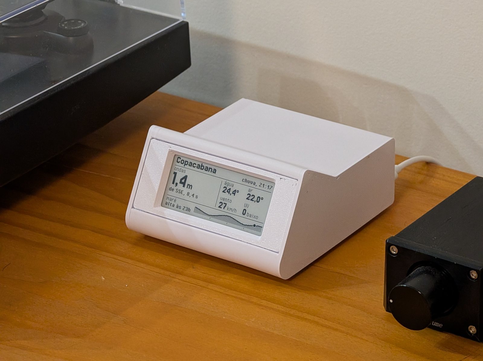
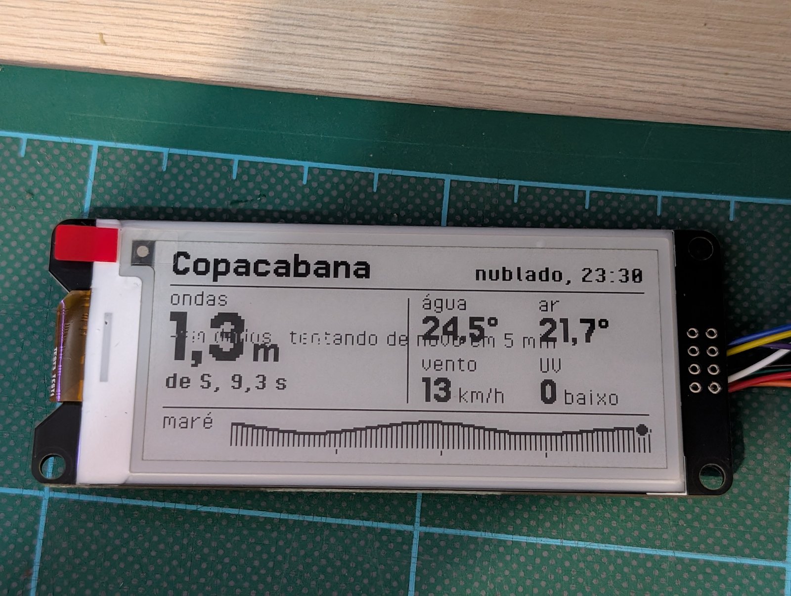
My wife swims in the ocean. Every now and then she gets to Copacabana and finds the sea too rough, or it starts raining hard in the middle of her swim and she has to get out of the water and go back home. I had a few ESP32-C3 Super Mini boards left over from home automation projects, and for a long time I had wanted to design something that existed outside a computer screen. I put the two things together and got what you see in the photo: a desk panel that shows the sea and weather conditions at Copacabana. Plug it in and that’s it.
I have introduced myself as a product designer for about thirteen years. That title used to mean only people who design physical products, and today it covers people who design software too, which has always been my case. I never imagined I would get to close that circle and design a product with electronic components and its own firmware, let alone alone, at home, without really knowing how to solder. What changed was having Claude on the other side of the conversation. This post is about how that went, including what went wrong.
What the panel does
From the user’s point of view, nothing. No buttons, no app, no settings. When you turn it on, it connects to Wi-Fi and shows:
- The place, the sky condition and the time.
- The wave height, with the direction they come from and the period in seconds.
- Water and air temperature, wind and UV index.
- The tide curve from 0h to 24h, with a dot at the current time and the next turn (“low at 18h”).
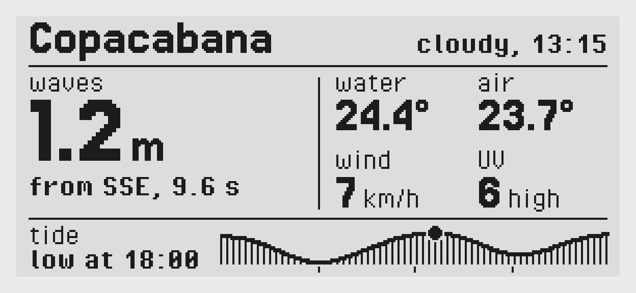
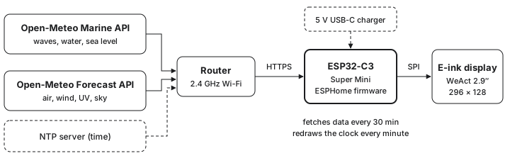
The data comes from Open-Meteo, an open API that needs no sign-up and no key. It is numerical model data, not a buoy on the beach: the point it queries is out at sea, about 7 km south of the sand, and the tide is calculated as well. It doesn’t replace the Navy’s tide tables, but for deciding whether it’s worth going down to the beach, it works very well.
The screen is e-paper (e-ink), 2.9 inches, 296 x 128 pixels, black and white. The data is fetched every 30 minutes, and the clock is redrawn every minute without flashing. Once in a while the screen does a full refresh, flashing for a couple of seconds to clear the “ghost” left by the previous numbers, just like a Kindle does.
Why not just open an app
Someone might ask why my wife doesn’t open Surfguru before leaving the house. It has far more information than this 2.9 inch screen, and it’s free. That’s true, and the panel shows less data on purpose. The information is only one part of the experience. The rest comes from a few qualities an app doesn’t have:
- It does one thing. No notifications, no feed, no ads, no other app one tap away.
- It’s always on and always in view. You can tell whether the sea is good while walking through the living room, without picking up the phone, unlocking it and opening something.
- It’s robust. Plug it in and it shows the same screen for months, with no app updates and no login that expires.
- It’s part of the house. It’s an object on the table, looking like an old radio, that matches the turntable next to it. An app doesn’t decorate anything.
This kind of product even has a name, calm technology, a term from Mark Weiser and John Seely Brown in the 1990s that Amber Case turned into a list of principles: technology that informs without demanding attention. It’s the difference between a wall clock and the clock on your phone. Both tell the time, but only one of them you check without interrupting what you were doing.
It started in an emulator
The first message I sent Claude was this:
I have some ESP32-C3 Super Minis here. I’d like to make a little device that simply shows the current sea and weather conditions at Copacabana beach, using real, up-to-date data, and displays it on a screen. No interaction needed, just show the data when the device turns on.
The answer was much more than I expected. Besides saying it could be done, it suggested Open-Meteo as the source, compared a color screen with an e-paper one, and built an emulator in the browser with both screens side by side, drawn with the data from that moment. I hadn’t bought anything yet and I was already looking at the final screen.
That set the way of working for the whole project: simulate before buying. Screen, fonts and layout were all decided in the emulator, and the firmware that runs on the board reproduces the same pixels. By the time the hardware arrived from AliExpress, the visual part was done.
The emulator is where the first good round of back and forth happened, about the fonts. Claude had used a bitmap Helvetica, and I asked for real pixel fonts, designed for a pixel grid. It measured the grid of every example I sent, drew the missing accented characters, and I applied the same rule I use in interfaces: at most three font sizes, with the big number as the exception. We ended up with Pixel Operator for text and Jersey 15 for numbers, and every pixel of the font lands exactly on a pixel of the screen.
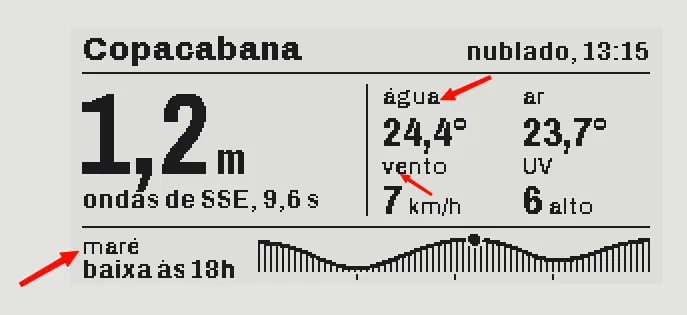
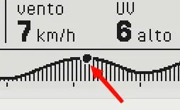
Pointing out the font rendering problems in the emulator
The parts
The list of components is short:
- An ESP32-C3 Super Mini, the generic three-dollar board that does Wi-Fi, fetches the data and draws the screen.
- A 2.9” WeAct Studio e-paper screen.
- The 8-wire cable that comes with the screen, plugged into pin headers soldered to the board.
- A 3D-printed case, in three parts.
- A USB-C cable and any phone charger.
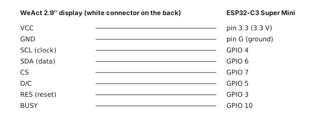
The firmware runs on ESPHome, which I already used at home with Home Assistant. The configuration is a YAML file, with the screen drawing in a block of C++ inside it. ESPHome runs on a Raspberry Pi at home, which compiles the firmware and sends it to the board over the network. After that the panel depends on nothing else: everything it does runs on the board.
With the components in hand, I asked for an assembly guide with steps, diagrams and the ESPHome file, which Claude compiled in its own environment before handing it to me. Keep that in mind, because it will matter in a moment.
The night of the first flash
This was the part with the most back and forth, and the one that taught me the most about working with AI on hardware. One night I sat down to flash the firmware for the first time, and it went wrong in four different ways, one after the other:
- The board’s port kept blinking in Chrome’s list. That was just the flashing mode, solved by holding two tiny buttons on the board.
- It flashed, but the screen didn’t change. Claude’s first mistake: the firmware only drew something once the data arrived, so any failure left the screen blank, with no clue. It changed it to draw “fetching data…” as soon as it turns on, which also tests whether the wires are right.
- The log showed Wi-Fi dropping all the time. Second mistake: to work around a known defect of the Super Mini, Claude had lowered the radio power, and lowered it too much for the distance to my router.
- It connected, and the board rebooted four seconds after calling the API.
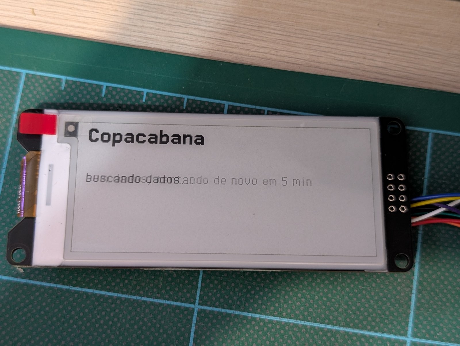
In the middle of this came my own share of the confusion. I was flashing old versions of the firmware without noticing:
Wait, I didn’t do anything with the yaml you sent. I don’t understand what the Yaml is and what the bin I download from ESPHome is
From then on I changed the arrangement: instead of sending me to hunt for lines in the code, it started updating the whole file, so I could just copy and paste it into ESPHome. It sounds silly, but it was one of the most important adjustments of the project. Whenever I had to edit a specific line of a file I didn’t understand, I got it wrong.
The fourth problem was the hardest. The API response came back empty, and the cause was that Claude had tested everything on the latest version of ESPHome, while my installation was months older, a version that didn’t read the response format Open-Meteo uses. It went into the source code of both versions to confirm the difference, I updated, and late that night the screen loaded data for the first time, with the ghost of the previous text behind the numbers.
The case
I wanted a case in the Dieter Rams style, inspired by the Braun DN40, the clock radio with the wedge profile. Claude got the profile wrong twice, because it was reading photos taken in perspective:
I don’t know where you got the idea that the DN40 has this valley. Its profile is straight, look at the image.
It got it right on the third try, when I sent a photo taken exactly from the side. The same thing happened with the screen’s connector, which it drew sticking out of the board until it saw a profile photo. I learned that visual references for an AI have to be photos from the side or the front, not in perspective.
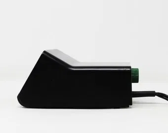
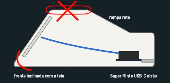
The reference I sent: the DN40 from the side. From this photo Claude understood there was a flat roof on top
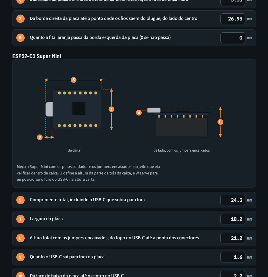
I took 26 measurements with a caliper (of the screen, the board, the connector and the plug) and filled them into a form it added to the guide. With that it modeled the case in Python and checked by calculation that nothing touched anything.
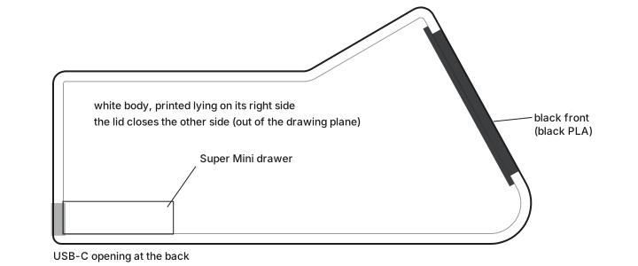
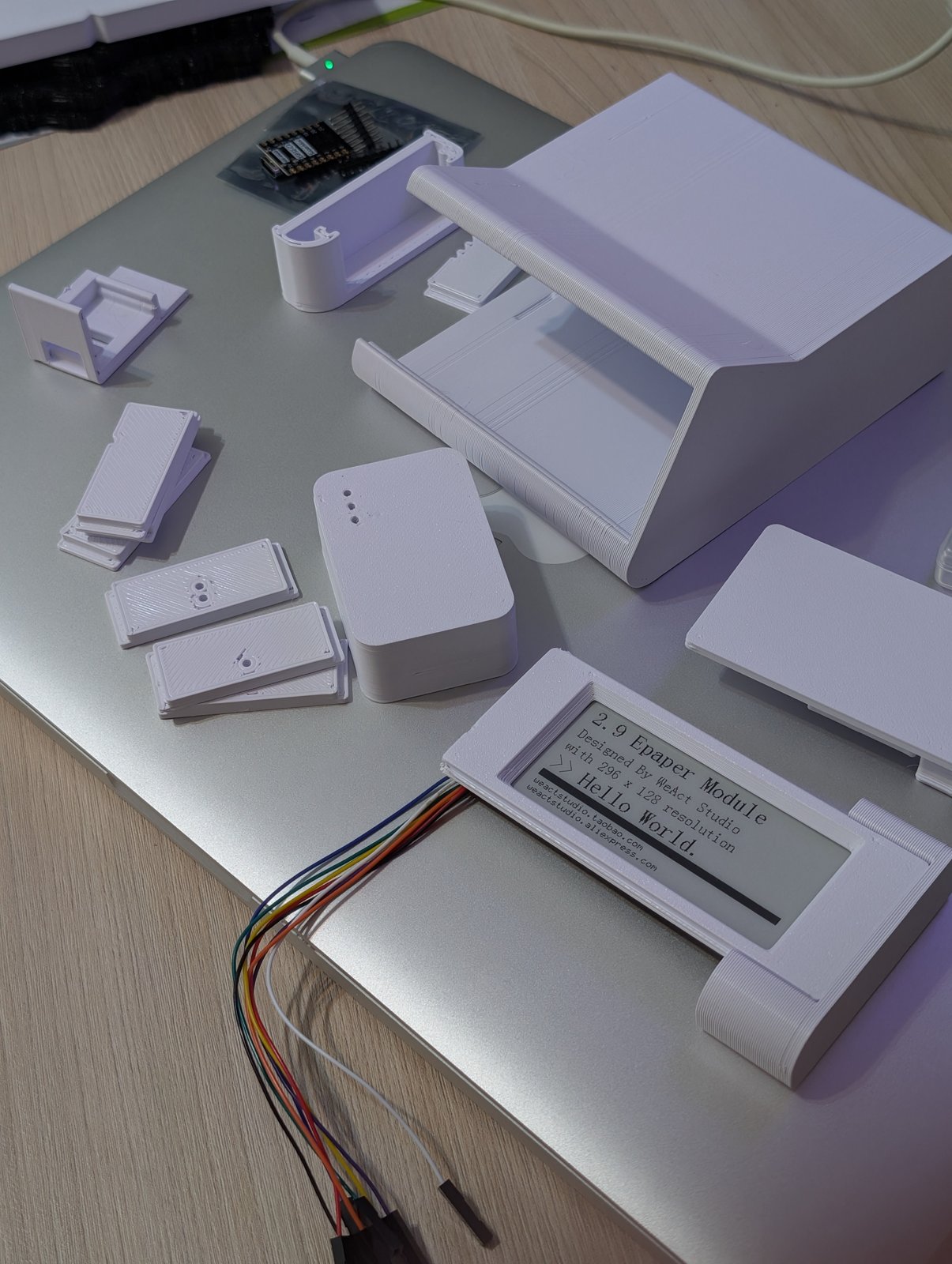
The case has three parts, no screws and no glue. The body, with one side closed and the other open, is printed lying down so it needs no supports. A lid closes the open side with four tabs that snap into internal channels. The front (black in the final model, like the DN40; mine, from the first print, came out all white) holds the screen with four pins and slides into rails in the body. The board slides into a drawer, with the USB-C pointing backwards.
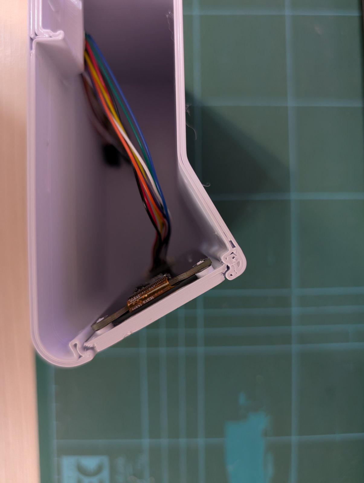
The first print had problems: the front went in so tight it cracked the edge of the body, the lid was loose, and the board sat at the bottom, out of reach. I glued everything and started using it. But since I want to print more units without having to sand or glue anything, calibration came next:
Remember I’m using a 0.8 nozzle on the printer, so you have to account for the final shape of the object being more distorted than the 3D model. We could do some test prints
Instead of printing the whole case again, Claude designed test pieces of a few grams for each joint. I suggested testing bigger slices directly on the body I already had, which saved plastic and time. And the result changed after the pieces cooled down: the one that fit best while warm wasn’t the best one cold. In the end we kept a sliding fit, with tiny bumps at three points of the rails to hold it.
Who did what
“Made with AI” can mean a lot of things, so let me be specific.
I bought the components, soldered, wired it up, flashed the firmware, pasted the logs, took the measurements, printed and assembled everything, judged every version of the screen and the case and set the design rules. I also corrected Claude every time it got a shape or an interpretation wrong, and offered a few engineering suggestions, like testing slices on the existing body.
Claude proposed the architecture and the data source, wrote all the code (emulator, firmware, font and case generators), diagnosed the bugs from the logs, wrote the guide, modeled the case and designed the test pieces.
And it got plenty wrong: the Wi-Fi power, the blank screen with no data, firmware tested on a different version than mine, the DN40 profile, the screen connector, the board out of reach in the first case, tolerances that ignored the printer’s thick nozzle. The difference is that none of those mistakes stayed hidden. When I pointed one out, it fixed it and said what it had gotten wrong.
The gift version
The original panel is on my desk. The next batch is for the friends who swim with my wife, and that changed the subject of the conversation: how do you hand this to someone who will never open a terminal in their life?
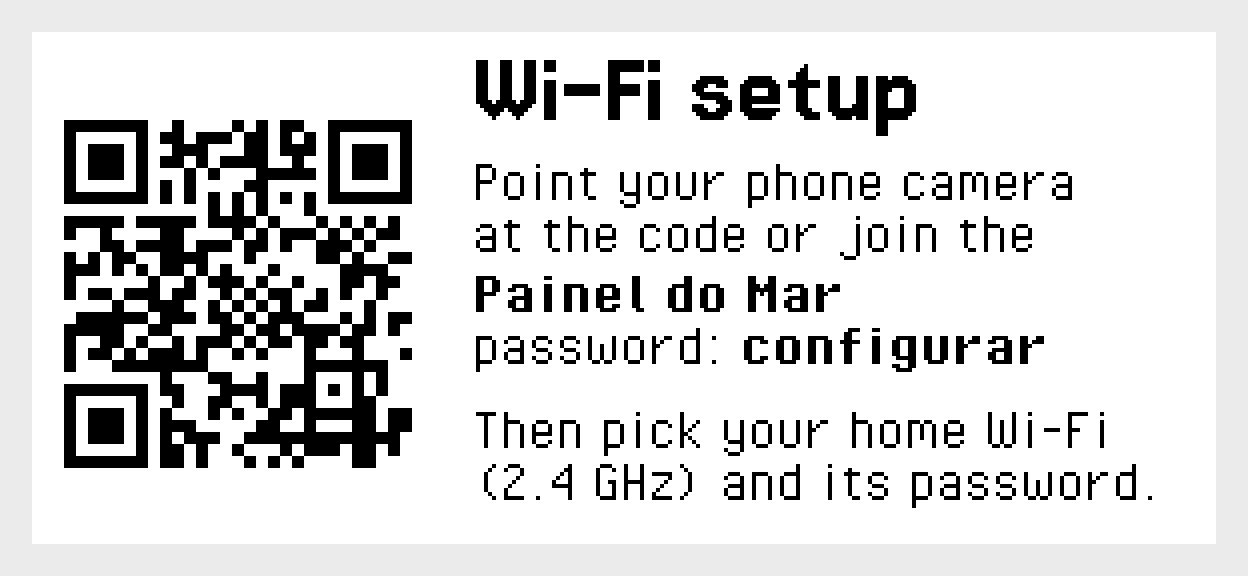
The gift version has a separate firmware. The first time it turns on, the board creates its own Wi-Fi network and the screen shows a QR code that connects the phone to it. A page opens by itself to pick the home network, and another QR code leads to a page where the person types their neighborhood or city. If there is no sea nearby, the screen becomes a weather panel. If the router changes, the screen goes back to setup mode on its own. And none of it depends on Home Assistant, because the people receiving it don’t have one.
What I learned
A few things I would take into the next hardware project with AI:
- Simulate before buying. The emulator with real data settled screen, fonts and layout before I spent a cent.
- Send the logs. Every firmware bug was solved from logs I pasted into the conversation. Without them, Claude’s hypotheses were wrong.
- The AI’s test environment is not yours. Now the first thing I tell it is the version of everything I have installed.
- 3D printing needs physical tests. The tolerance that was right in the model came out wrong on a printer with a 0.8 mm nozzle.
- Say how you want to receive things. The conversation went much better once I asked for whole files instead of instructions to edit lines. The AI doesn’t know how much you know until you tell it.
I spent thirteen years designing software. This is the first product I can hold in my hand, and the best part wasn’t Claude writing the code. It was being able to discuss case profiles, joint tolerances and radio power with someone who answered on the spot, got things wrong, owned up to it and tried again, until the object was the way I wanted it.
P.S.: If you want to build your own, the parts list is up there and ESPHome has very good documentation for this screen. Let me know if you do 😉